________________________________________________________________________________
Case IH 885, 485 Tractor Steering Cylinder
Various types of steering cylinders are used depending on front axle
type.
Case IH 885, 485 Tractor Steering
Cylinder seal test
To check steering cylinder seals, operate engine at low idle speed. Turn
steering wheel from lock to lock at least four times to remove all air
from the system.
Turn wheels fully to the left and stop the engine. Disconnect steering
hose from left end of steering cylinder.
Connect a high pressure cap on steering hose. Allow any oil to flow from
the open union on steering cylinder. Start engine and operate at low
idle speed.
Check for oil leaking from open union and at the right steering shaft
seals in end cap.
A small amount of oil (up to 5 drops in 30 seconds) is permissible for
leakage past the piston seals. There should be no leakage at shaft seals
in end cap. If cylinder tests OK, repeat the test on right end of
cylinder.
Case 885, 485 Tractor With Adjustable
Front Axle
OVERHAUL
To remove the steering cylinder, first, disconnect steering hose at each
end of cylinder. Plug or cap all openings. Remove the clevis pin at
right end of cylinder shaft.
Straighten lockstrip and unbolt lower pivot arm. Remove lower arm, then
remove clevis end from anchor on axle main member. Lower cylinder
assembly from upper pivot arm.

Fig.5. Exploded view of steering cylinder used on Case 485, 885 Tractor
with adjustable front axle
To disassemble the cylinder, first clean exterior of cylinder and clamp
lower pivot flange in a soft jawed vise. Remove elbow fitting (11—Fig.5)
from left end of cylinder rod and clevis (15) from right end.
Lift end of retaining ring (13) out of slot, then using a pin type
spanner, rotate cylinder head (6) and work retaining ring out of its
groove.
Cylinder rod and piston assembly (3) can now be removed from cylinder
tube (12). Remove remaining cylinder head in the same manner. All seals,
"o" rings and back-up rings are now available for inspection and/or
renewal.
Clean all parts in a suitable solvent and inspect. Check cylinder tube
(12) for scoring, grooving and out-of-roundness. Light scoring can be
polished out by using a fine emery cloth and oil, providing a rotary
motion is used during polishing operation.
A cylinder tube that is heavily scored or grooved, or is out-of-round,
should be renewed. Check piston rod and piston (3) for scoring, grooving
and straightness. Polish out very light scoring with fine emery cloth
and oil, using a rotary motion.
Renew rod and piston assembly if heavily scored or grooved, or if piston
rod is bent. Inspect bores of cylinder heads (6) and renew same if
excessively worn or out-of-round. All "O" rings, seals, back-up rings
and retainer rings are available in a seal kit. Lubricate ail "O" rings,
back-up rings and seals during assembly.
Reassemble steering cylinder as follows: Install a new "o" ring (2) in
groove of piston, then follow with new seal ring (1). Install "o" ring
(7), back-up ring (8) and wiper seal (9) in each cylinder head (6) and
back-up ring (5) and "o'' ring (4) over each cylinder head.
Using a ring compressor or suitable hose clamp around piston seal ring
(1), install piston and rod assembly. Install cylinder head assemblies
over each end of piston rod and into cylinder tube. Align hole in groove
of cylinder heads so they will accept nib on end of retaining rings
(13).
Rotate cylinder heads until retaining rings are pulled completely into
cylinder tube. Using new "o" rings (10 and 14), install elbow (11) in
left end of cylinder rod and clevis (15) on right end. Tighten clevis to
a torque of 170-180 ft.-lbs (230-244 N-m).
Reinstall cylinder on tractor by reversing removal procedure. Tighten
lower arm retaining cap screws to a torque of 80-90 ft.-lbs. (110-124
N-m). Bend corners of lock plate up against flat on cap screw heads.
Bleed air from power steering.
Case 885, 485 Tractor With
Nonadjustable (Cast) Front Axle
OVERHAUL
To remove the steering cylinder, first disconnect steering hose at each
end of cylinder. Disconnect steering cylinder ball joint end from left
steering arm. Remove pivot pin at right end of cylinder. Then, lift
cylinder from tractor. Drain oil from cylinder, then thoroughly clean
exterior of cylinder.

Fig.6. Exploded view of steering cylinder used on Case IH 485,
885 Tractor equipped with nonadjustable (cast) front axle
To disassemble steering cylinder, clamp the flat end of steering tube
(1—Fig. 6) in a soft jawed vise so cylinder is in vertical position.
Remove smalt slot head lock screw (9) and lockwasher from cylinder.
Use a filter wrench CAS-04-535 or equivalent, rotate cylinder
counterclockwise until the straight end of retaining ring (5) can be
seen through slot in cylinder.
Pry end of retaining ring out through slot and continue to turn cylinder
counterclockwise until ring is removed. Pull steering rod and cylinder
assembly from the tube (1).
Remove seal ring (2), back-up ring (8) and "O" ring (4) from end of
steering tube. Place steering rod ball joint in the vise, remove
clamping bolt, then remove ball joint.
Lightly clamp cylinder in the vise and pull rod and piston (6) from
cylinder. Remove wiper seal (13) and seal ring (12) from cylinder and
seal ring (8) and "o" ring (7) from piston.
Clean and inspect all parts. Inspect cylinder (11) for scoring or
out-of-roundness. Light scoring can be polished out using a fine emery
cloth and oil, providing a rotary motion is used during polishing
operation.
Renew cylinder if heavily scored or out-of-round. Check piston rod and
piston (6) for scoring and straight ness. Polish out light scoring with
fine emery cloth and oil, using a rotary motion.
Renew rod and piston assembly if heavily scored or if rod is bent. All
"O" rings, back-up rings, seal rings and wiper seal are available in a
seal kit. Lubricate all internal parts with Hy-Tran Plus fluid during
reassembly.
Reassemble steering cylinder by reversing the disassembly, keeping the
following points in mind: Heat Teflon seal rings and back-up rings in
clean Hy-Tran Plus oil to a temperature of 75° F (24° C) to make them
more flexible. Tighten clamping bolt on ball joint to a torque of 60-65
ft.-lbs. (81-85 N-m).
For aid in installation, set distance from center of pivot pin hole to
center of ball joint to 35-1/2 inches (905 mm). With front wheels in
straight ahead position, reinstall cylinder assembly.
Tighten ball joint nut to a torque of 50-100 ft.-lbs. (68436 N-m) and
secure with cotter pin. When installation of cylinder is complete, bleed
air from power steering.
Case 485, 885 Tractor With Front Drive
Axle

Fig.7. Steering cylinder Is contained In back side of front
drive axle housing
OVERHAUL
The Case IH 885, 485 Tractor power steering cylinder is contained in the
back side of front drive axle housing. See Fig.7. Cylinder can be
disassembled without removing axle assembly.
Disconnect steering lines at each end of cylinder. Cap or plug all
openings immediately. Clean exterior of cylinder and surrounding area.
Disconnect tie rod ends from swivel housing arms. Unbolt and remove
steering stop collar at each end of cylinder rod. Remove tie rods by
unscrewing threaded studs (3) from ends of cylinder rod.
Unbolt and remove right side guide (22—Fig. 8) and shim spacer (20).
Withdraw piston and rod assembly, then remove cylinder sleeve (6) and
left side guide (4).
Remove scraper (2) and groove rings (3) from both end guides. Remove the
two Teflon rings (8) and piston seal ring (9) from piston.
Remove snap ring (10), collar ring (11) and split ring (12), raise, then
tower piston and remove spacer (13) and "O" ring (14). Remove piston
(15), spacer (16), split ring (17), collar ring (18) and snap ring (19).

Fig.8. Exploded view of steering cylinder used on Case 885, 485
Tractor equipped with front drive axle
Clean and inspect all parts for excessive wear or other damage. Inspect
cylinder sleeve (6), piston (15), rod (23) and rod guides (4 and 22) for
cracks, scoring or other damage.
Light scoring can be polished out using fine emery cloth and oil,
providing a rotary motion is used during the polishing procedure. Use
all new "0" rings, seals and seal rings and lubricate with clean Hy-Tran
Plus fluid during reassembly.
Reassemble cylinder by reversing disassembly procedure and adjust
cylinder sleeve to zero end play as follows: With lips of grooved ring
(3) and scraper ring (2) facing inward and "o" ring (1) in external
groove, install left rod guide (4) with notch facing hydraulic port.
With "o" rings (5 and 7) installed in grooves of cylinder sleeve,
install sleeve until fully seated on left rod guide.
Measure distance between outer and inner faces of right side rod guide
and record the distance. Then, measure distance between axle housing and
end of cylinder sleeve and record the distance.
Subtract the second distance from the first distance to determine
correct thickness of shim spacer (20— Fig.8) to be used.
Shim spacers are available in thicknesses of 0.035 to 0.071 inch (0.9 to
1.8 mm) in increments of 0.004 inch (0.1 mm). Install rod and piston
assembly in cylinder sleeve.
With lips of grooved ring (3) and scraper ring (2) facing inward in
right side rod guide, use vaseline to stick the determined shim spacer
to inside of rod guide. Install right side rod guide and tighten rod
guide cap screws to a torque of 52 ft .-lbs. (70 N-m).
Apply Loctite 242 to the first three threads and install threaded studs
(3—Fig. 7) in cylinder rod ends.
________________________________________________________________________________
________________________________________________________________________________________
________________________________________________________________________________________
| CASE IH TRACTORS SPECIFICATIONS |
________________________________________________________________________________________
________________________________________________________________________________________
________________________________________________________________________________________
________________________________________________________________________________________
________________________________________________________________________________________
________________________________________________________________________________________
________________________________________________________________________________________
________________________________________________________________________________________
________________________________________________________________________________________
________________________________________________________________________________________
________________________________________________________________________________________
________________________________________________________________________________________
| CASE IH FRONT END LOADERS SPECS |
________________________________________________________________________________________
________________________________________________________________________________________
________________________________________________________________________________________
________________________________________________________________________________________
________________________________________________________________________________________
________________________________________________________________________________________
________________________________________________________________________________________
________________________________________________________________________________________
________________________________________________________________________________________

 CASE IH SPECS
 J.I. CASE SPECS
 PROBLEMS
 LOADERS
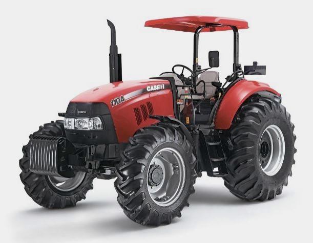 FARMALL 110A
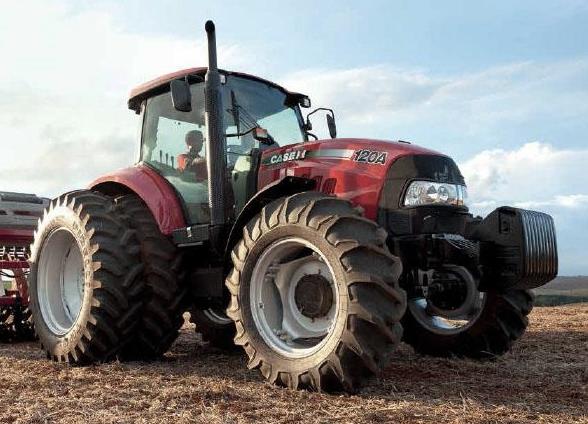 FARMALL 120A
 FARMALL 30C
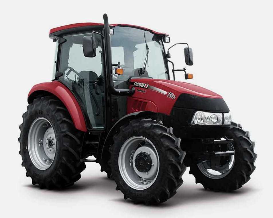 FARMALL 75C
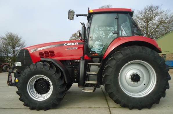 MAGNUM 280
 580E Backhoe
 580L Backhoe
 580N Backhoe
 580 Super L
 580SM Backhoe
 580SLE Backhoe
 580SN Backhoe
 580M Backhoe
 580 Super E
 580ST Backhoe
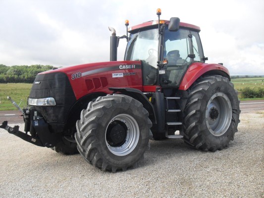 MAGNUM 310
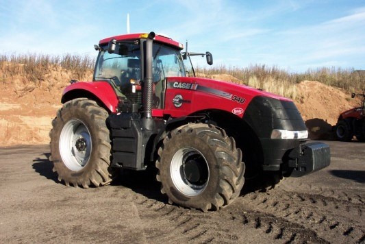 MAGNUM 340
 MAXXUM 110CVX
 MAXXUM 120CVX
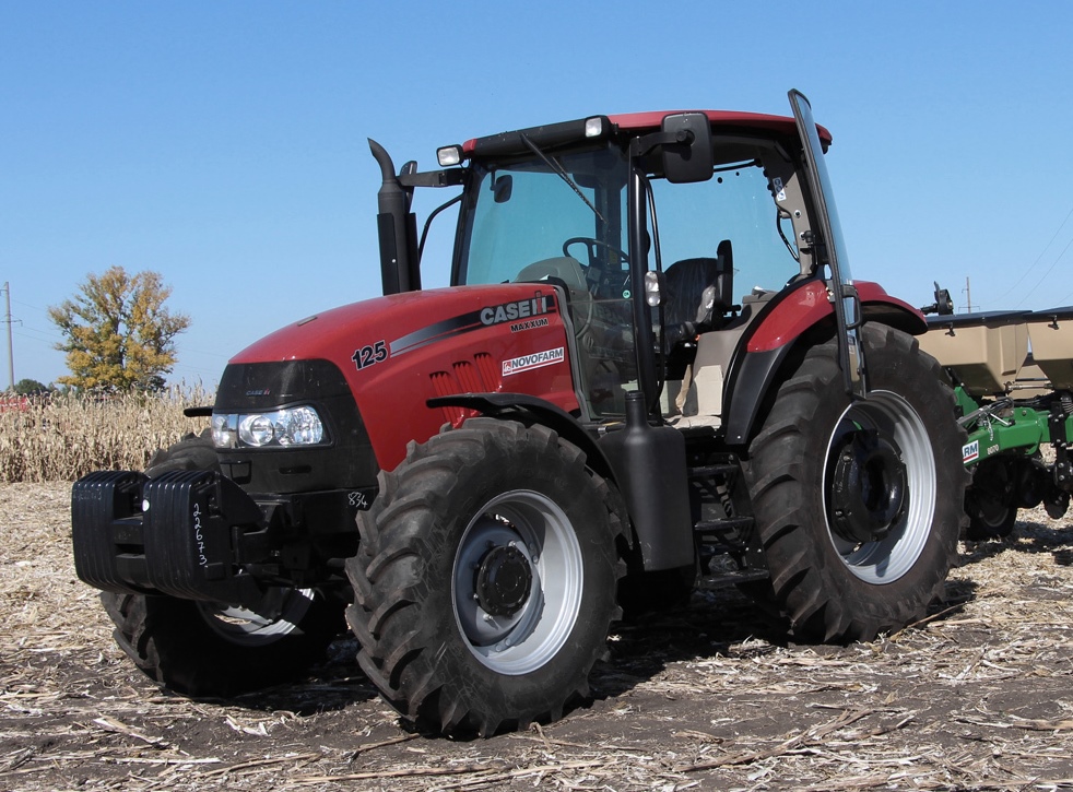 MAXXUM 125
 1394
1394 1455XL
 1494
1494 1594
1594 3230
3230 4210
4210 585XL
585XL 633
633 695XL
695XL 733
733 MX110
MX110 MX135
MX135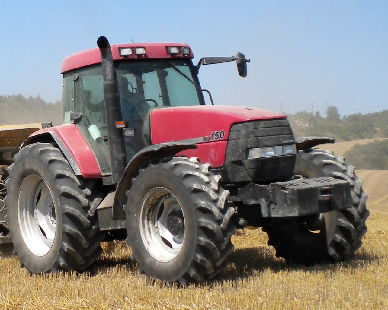 MX150
MX150 MXU110
 MXU135
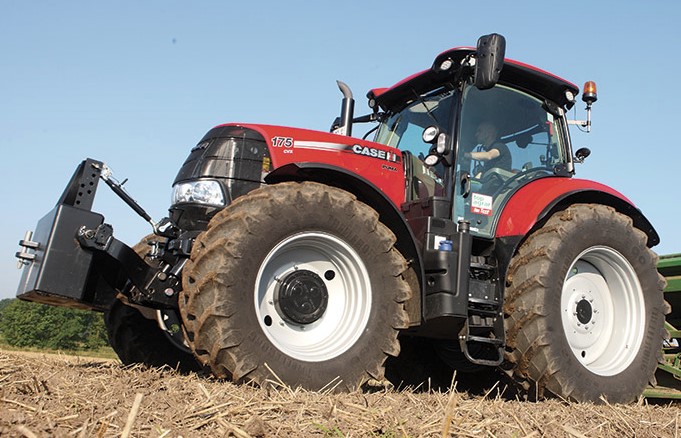 PUMA 175CVX
 PUMA 185CVX
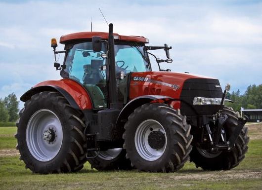 PUMA 200CVX
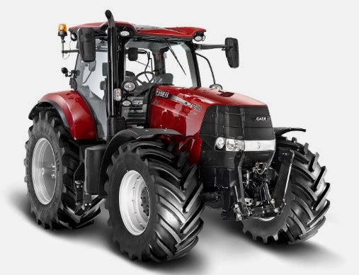 PUMA 240CVX
 OPTUM 300
 FARMALL 50B
 FARMALL 95U
 FARMALL 125A
 PUMA 150
 PUMA 165
 MAGNUM 210
 MX 170
 MAXXUM 150
 OPTUM 270
 MAGNUM 315
 FARMALL 70
 FARMALL 75N
 FARMALL 95C
 FARMALL 105N
 FARMALL 30B
 L103 Loader
 L104 Loader
 L105 Loader
 L106 Loader
 L107 Loader
 L108 Loader
 L130 Loader
 L160 Loader
 L300 Loader
 L340 Loader
 L350 Loader
 L360 Loader
 L530 Loader
 L540 Loader
 L545 Loader
 L550 Loader
 L555 Loader
 L560 Loader
 L565 Loader
 L570 Loader
 L575 Loader
 L720 Loader
 L730 Loader
 L735 Loader
 L740 Loader
 LRZ 95
 LRZ 100
 LRZ 120
 LRZ 130
 LRZ 150
 L745 Loader
 L750 Loader
 L755 Loader
 L760 Loader
 L765 Loader
 L770 Loader
 L775 Loader
 L780 Loader
 L785 Loader
 L795 Loader
 90 Loader
 890 Loader
 2200 Loader
 2250 Loader
 LX156 Loader