________________________________________________________________________________
Forward-reverse transmission of Case IH 685, 885 Tractor - Forward-reverse unit
Overhaul
To remove the Forward-Reverse unit, speed gearbox must be removed from
Case 385, 485, 585, 685, 885 tractors, to remove the speed gearbox,
first remove cab and fuel tanks or fenders, tank and platform.
Remove plugs and drain fluid from speed gearbox and rear frame. Remove
front drive axle drive shaft and shield if so equipped. Unbolt and
remove pto clutch cover from bottom of rear main frame.
Drive roll pin from pto clutch and shaft. Unbolt lower pto shaft cover
or seal housing, as equipped, and remove with gasket from rear of
tractor. Have helper support the pto clutch.
Withdraw lower pto shaft and remove pto clutch. Unbolt and remove bottom
core plate and regulator valve. Remove oil inlet tube from
Forward-Reverse clutch housing.
Disconnect 1st-2nd and 3rd-4th selector rods from gear selector levers.
Disconnect all interfering hydraulic lines and wiring. Using a sling and
hoist, lift off steering support assembly.
Remove right and left brake pipes. Remove steering supply and return
pipes and oil cooler supply and return pipes.
Plug or cap all openings immediately to prevent foreign material from
entering systems. Disconnect and remove the Case 685, 885
Forward-Reverse lockout mechanism from speed selector cover.
Place special tool or equivalent, under tractor. Adjust splitting tool
to support tractor under speed gearbox and rear main frame.
Place wooden wedges between front axle and front support to prevent
tipping.
Unbolt range section (rear frame) from speed gearbox. After making
certain that all wires and hydraulic lines are disconnected, roll engine
and speed gearbox assembly forward from range section.
Attach a sling and hoist to speed gearbox and block up securely under
engine oil pan. Unbolt clutch housing from engine, then separate speed
gearbox from engine.
If available, attach speed gearbox assembly in a transmission stand.
Remove clutch release bearing and sleeve. Drive roll pins from release
fork, withdraw release shaft and remove fork. Unbolt and remove pto
driven shaft end cover and metal gasket as shown in Figure.
Remove snap ring from front end of pto driven shaft. Working through
bottom core plate opening, remove snap ring from pto driven gear.
Drive the driven shaft rearward out of bearing and remove bearing.
Withdraw the driven shaft and have helper remove gear as shaft is
removed.
Unbolt and remove clutch release sleeve carrier, then withdraw pto drive
shaft and gear. Remove snap ring from front end of countershaft and
remove the reverse gear from countershaft.
Drive expansion plug from front of speed gearbox. Drive out the two roll
pins from reverse idler shaft. Install a 1/4 x 8 inch NC bolt through
the expansion plug hole and into reverse idler shaft.
Pull out the idler shaft and remove the reverse idler gear.
Unpin the Forward-Reverse actuating lever from speed selector cover,
then turn lever clockwise to disengage lever from spool valve. Remove
speed selector cover, selector shafts and forks.
Remove the Forward-Reverse unit from front of speed gearbox. Remove
pressure tubes and "O" rings (3).

Fig.3. Case 685, 885 Forward-Reverse transmission. Item (25
through 31) are located in speed gearbox
1.Snap ring, 2.Washer, 3.Needle hearing, 4.Idler gear, 5.Washer,
6.Sleeve, 7.Roll pin, 8.Snap ring, 9.Shaft, 10.Roll pin, 11.Oil seal,
12.Pto shaft seal, 13.Clutch shaft seal, 14."O" ring, 15.Retaining ring,
16.Collar, 17.Forward-reverse shift spool, 18.Housing, 19."O" ring,
20.Seal rings, 21.Retaining ring, 22.Ball bearing, 23.Snap ring,
24.Thrust washer, 25.Needle bearing, 26.Forward drive gear & hub,
27.Needle bearings, 28.Ball bearing, 29.Clutch disc carrier, 30.Snap
ring, 31.Retaining ring, 32.Retaining ring, 33.Oil deflector, 34.Clutch
assy, 35.Drive gear, 36.Woodruff key, 37.Clutch shaft, 38.Snap ring,
39.Countershaft reverse gear, 40.Snap ring, 41.Countershaft
To disassemble the removed Forward-Reverse unit and proceed as follows:
Clamp clutch shaft (37) in a soft jawed vise and remove shift spool (17)
from housing (18).
Remove retaining ring (32) and oil deflector (33). Using a suitable
puller, remove Forward-Reverse clutch unit (34).
Remove Woodruff key (36), then remove drive gear (35). Remove snap ring
(23) and slide housing (18) from clutch shaft.
Unlock and remove the three seal rings (20) and remove retaining ring
(21). Press shaft from bearing (32) and remove thrust washer (24).

Fig.4. Case IH 685, 885 tractor Forward-Reverse clutches
1.Retaining ring, 2.Clutch back plate, 3.Friction disc (4), 4.Separator
plates (3), 5.Piston back plate, 6.Shim, 7.Piston, 8.Nut (3), 9,"O"
ring, 10."O" ring, 11.Clutch cup, 12."O" ring, 13."O" ring, 14.Piston,
15.Spacer (3), 16.Bolt (3), 17,Shim, 18.Piston back plate, 19.Separator
plates (3), 20,Friction discs, 21.Clutch back plate, 22.Retaining ring
To disassemble the clutch unit (34), place unit in a press (either end
up) and apply pressure to clutch plates, then remove retaining ring (1).
Remove clutch back plate (2), friction discs (3), separator plates (4),
piston back plate (5) and shim (6). Turn clutch cup (11) over and
compress clutch plates, then remove retaining ring (22).
Remove clutch back plate (21), friction discs (20), separator plates
(19), piston back plate (18) and shim (17). Using an Allen wrench,
remove bolts (16) and nuts (8).
Bump clutch cup (11) on a bench and remove piston (7) and spacers (15).
Turn clutch cup over and bump out piston (14). Remove "O" rings (9, 10,
12 and 13) from pistons.
Clean and inspect all parts and renew any showing excessive wear or
other damage. When reassembling, use all new "O" rings, seal rings,
gaskets and oil seals.
Before installing any new friction discs (3 or 20), soak new discs in
clean Hy-Tran Plus fluid for three minutes.
When installing pistons, tighten new bolts (16) and nuts (8) to a torque
of 6 ft.-lbs. (8 N-m), then stake the nuts. Reassemble clutches in
clutch cup but install one 0.024 inch (0.61 mm) shim (6).
Do not install any shim (17) at this time. Install clutch assembly in a
press with the side with shim (6) at the top.
Apply a load of 22-30 lbs. (98-133 N) and using a feeler gage, measure
the clearance between clutch back plate (2) and retaining ring (1).
Clearance should be between 0.044 and 0.060 inch (1.117 to 1.524 mm). If
the clearance is greater than 0.060 inch (1.524 mm), slums must be
added.
If clearance measures less than 0.044 inch (1.117 mm), a thinner shim
must be installed. When correct clearance is obtained, remove and
measure thickness of shim and divide by 2, equally as possible.
For example, if shim measures 0.024 inch (0.61 mm), install one 0.014
inch (0.355 mm) thick shim on each clutch half. Shims are available in
thicknesses of 0.014, 0.024 and 0.036 inch (0.355, 0.61 and 0.914 mm).
Reassemble and reinstall Forward-Reverse transmission by reversing the
disassemble and removal procedures, keeping the following points in
mind: Apply Loctite 515 to mounting face of range section, then
reconnect speed gearbox to range section.
Tighten bolts securing speed gearbox to engine and speed gearbox to
range section to a torque of 80 ftlbs. (108 Nm).
________________________________________________________________________________
________________________________________________________________________________________
________________________________________________________________________________________
| CASE IH TRACTORS SPECIFICATIONS |
________________________________________________________________________________________
________________________________________________________________________________________
________________________________________________________________________________________
________________________________________________________________________________________
________________________________________________________________________________________
________________________________________________________________________________________
________________________________________________________________________________________
________________________________________________________________________________________
________________________________________________________________________________________
________________________________________________________________________________________
________________________________________________________________________________________
________________________________________________________________________________________
| CASE IH FRONT END LOADERS SPECS |
________________________________________________________________________________________
________________________________________________________________________________________
________________________________________________________________________________________
________________________________________________________________________________________
________________________________________________________________________________________
________________________________________________________________________________________
________________________________________________________________________________________
________________________________________________________________________________________
________________________________________________________________________________________

 CASE IH SPECS
 J.I. CASE SPECS
 PROBLEMS
 LOADERS
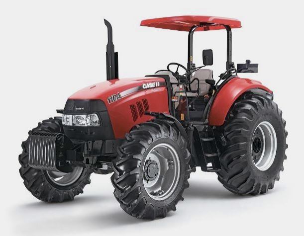 FARMALL 110A
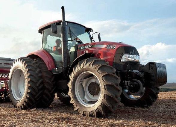 FARMALL 120A
 FARMALL 30C
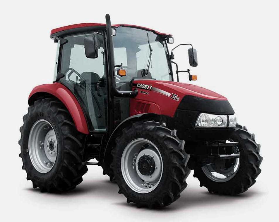 FARMALL 75C
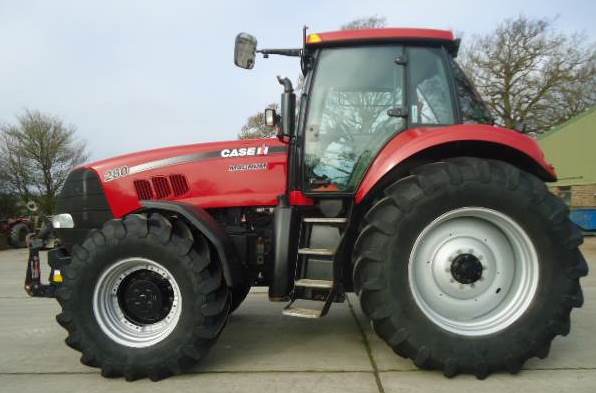 MAGNUM 280
 580E Backhoe
 580L Backhoe
 580N Backhoe
 580 Super L
 580SM Backhoe
 580SLE Backhoe
 580SN Backhoe
 580M Backhoe
 580 Super E
 580ST Backhoe
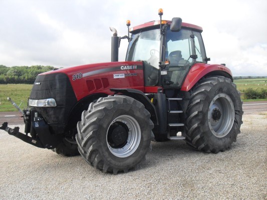 MAGNUM 310
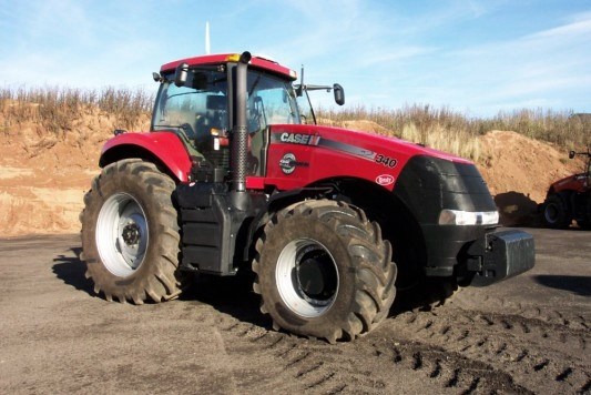 MAGNUM 340
 MAXXUM 110CVX
 MAXXUM 120CVX
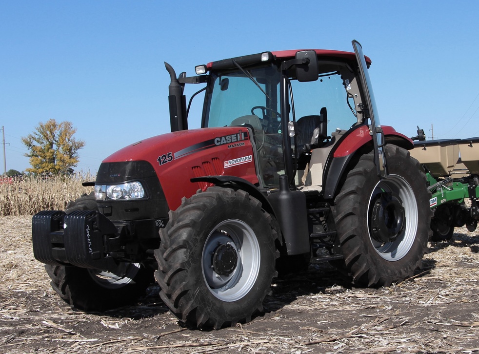 MAXXUM 125
 1394
1394 1455XL
 1494
1494 1594
1594 3230
3230 4210
4210 585XL
585XL 633
633 695XL
695XL 733
733 MX110
MX110 MX135
MX135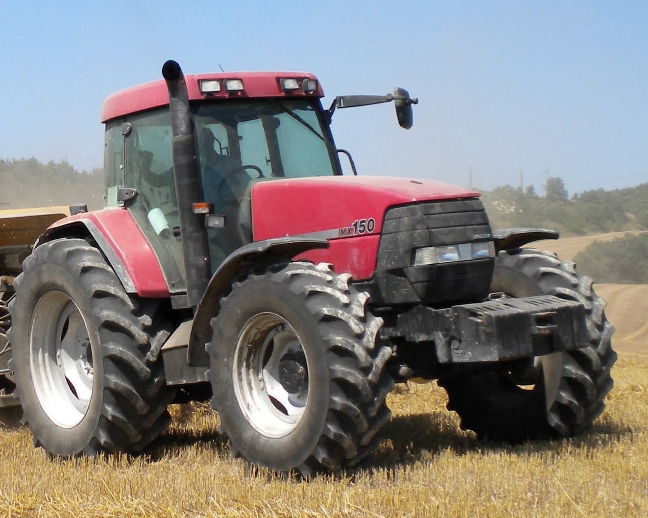 MX150
MX150 MXU110
 MXU135
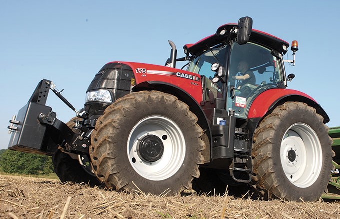 PUMA 175CVX
 PUMA 185CVX
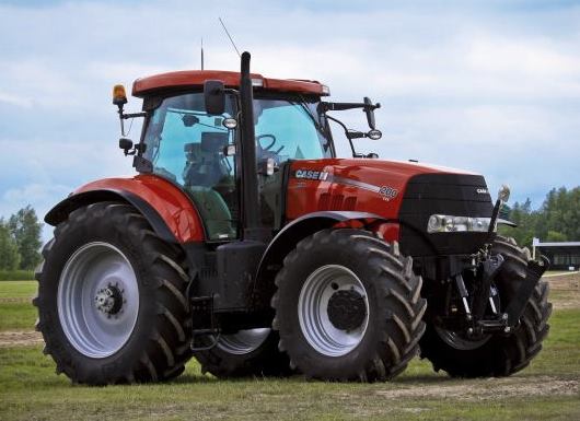 PUMA 200CVX
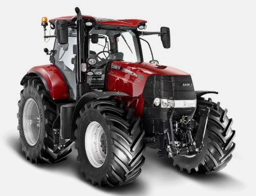 PUMA 240CVX
 OPTUM 300
 FARMALL 50B
 FARMALL 95U
 FARMALL 125A
 PUMA 150
 PUMA 165
 MAGNUM 210
 MX 170
 MAXXUM 150
 OPTUM 270
 MAGNUM 315
 FARMALL 70
 FARMALL 75N
 FARMALL 95C
 FARMALL 105N
 FARMALL 30B
 L103 Loader
 L104 Loader
 L105 Loader
 L106 Loader
 L107 Loader
 L108 Loader
 L130 Loader
 L160 Loader
 L300 Loader
 L340 Loader
 L350 Loader
 L360 Loader
 L530 Loader
 L540 Loader
 L545 Loader
 L550 Loader
 L555 Loader
 L560 Loader
 L565 Loader
 L570 Loader
 L575 Loader
 L720 Loader
 L730 Loader
 L735 Loader
 L740 Loader
 LRZ 95
 LRZ 100
 LRZ 120
 LRZ 130
 LRZ 150
 L745 Loader
 L750 Loader
 L755 Loader
 L760 Loader
 L765 Loader
 L770 Loader
 L775 Loader
 L780 Loader
 L785 Loader
 L795 Loader
 90 Loader
 890 Loader
 2200 Loader
 2250 Loader
 LX156 Loader