________________________________________________________________________________
Massey Ferguson 5445, 5465, 5475 PTO - Shiftable shaft
The power take-off shaft is freely mounted in the bearing (2) and force fitted in the bearing (10). The bearings are fitted into the rear axle housing and unit (14) respectively. The hub of the coupler (5) is splined to the shaft (13). These gears (4) (7) drive the shaft when the coupler (5) is moved either forwards (540 rpm) or backwards (1000 rpm).
When one of the gears (4) or (7), fitted with the rings (19) (20)
respectively is passive, it turns either on the ring (3) or on the shaft
(13). A fork (25) fitted to the pin (22) selects the 540 or the 1000 rpm
speed. Sealing is obtained via the seal ring (11) and the "O" ring (18).
The deflector (12) prevents contamination by foreign material. Depending
on option, the power take-off shaft may be supported by tapered roller
bearings. Another version with a flanged shaft makes it possible to
rapidly change the end fitting (32) (6 or 21 splines).
Lubricating the gears
The transmission oil provides lubrication for the two gears. The bearing
(2) has a sealed face turned towards the 540 rpm gear. Lubrication of
the gears is obtained via the oil receiver (1) and the shaft (13)
provided with an axial gallery and radial ports.

Parts list - (1) Oil receiver (2) Bearing (3) Ring (4)
Gear (540 rpm) (5) Coupler (6) Hub (7) Gear (1000 rpm) (8) Circlip (9)
Snap ring (10) Bearing (11) Seal ring (12) Deflector (13) PTO shaft (14)
Unit (15) Screw (15A) Screw (16) Sensor (17) Nut (18) "O" ring (19) Ring
(20) Ring (21) Rod (22) Pin (23) "O" ring (24) Pads (25) Fork (26) Set
screw (27) Special spacers (28) Plug (29) "Bayonet" protective cap (30)
Protective screw cap (31) Flanged shaft (32) End fitting (6 or 21
splines) (33) Dowels (34) Screw

MF 5435, 5445, 5455, 5460, 5465, 5470, 5475 -
Removing and refitting the rear bearing
Removal
Partially drain the rear axle housing. Engage the coupler (5) on the
gear (7). Remove the two diametrically opposing screws (15). In their
place, tighten two guide studs up against the gear (7). The purpose of
this operation is to hold the gears (4) and (7) and the hub and coupler
in line when removing the shaft (13) and the bearing assembly. Remove
the other two screws (15). Remove the shaft and the bearing assembly.
Discard the seal (18).
Refitting
Replace the seal (18). Fit the shaft and the bearing assembly. Smear two
screws (15) with Loctite 542 and tighten them to 105-120 Nm. Remove the
two guide studs. Smear and tighten the other two screws. Top up the oil
level of the rear axle housing and check it using the gauge located to
the rear of the centre housing.
Massey Ferguson 5435, 5445, 5455, 5460, 5465,
5470, 5475 - Disassembling and reassembling the rear bearing
Disassembly
Remove the rear bearing. Remove the "O" ring (18). Remove the circlip
(8). Separate the cover plate (14) from the bearing (10). Remove snap
ring (9). Extract bearing (10) from shaft (13). Extract the seal ring
and deflector (12).
Reassembly
Using a press and a suitable fixture, fit the deflector (12) up against
the cover plate in the correct direction. Using a press and a suitable
fixture, fit the seal ring (11) level with the chamfer machined on the
cover plate (14), with the lip turned towards the bearing (10). Fit the
unit (14), carry out steps in reverse order and refit the rear bearing.
MF 5435, 5445, 5455, 5460, 5465, 5470, 5475 -
Disassembling and reassembling the 540 rpm and 1000 rpm gears and the
front shaft bearing
Before removing the gears (4) (7), it is necessary to remove: linkage
cover plate; hitch hook support; PTO top cover plate located at the rear
of the tractor, the double driving gear and, if applicable, the control
fork (4-speed economy PTO).
Disassembly
Remove the left-hand lift ram and take off the PTO sensor. Undo the set
screw (26). Take out the pin (22) with the rod (21) towards the
left-hand side of the tractor, and discard the "O" ring (23). The plug
(28) remains inside the housing. Take out the fork (25) with the pads
(24) without letting them fall into the housing. Remove the rear
bearing. Remove the hub (6) with the coupler (5), the gears (4) (7) and
the ring (3). Extract the bearing (2) and the oil receiver (1).
Reassembly
Check and clean the components. Replace any defective parts. Lightly
smear the oil receiver (1) with Loctite 648 or equivalent on the face
turned towards the centre housing. Fit the receiver with the opening
facing upwards. Insert the bearing (2) into the housing against the oil
receiver (1). Turn the sealed part of the bearing towards the gear (4).
Using a jet of compressed air, check that the channel in the shaft (13)
is not obstructed.
Lubricate the rings (19) (20). Refit the gears (4) (7) and the coupler
(5)with the hub (6) and the ring (3), with the opening of the teeth
turned towards the rear of the tractor. If the rings (19) (20) are
damaged (not referenced in the spare parts catalogue), then replace the
gears (4) (7). Engage the coupler (5) on the gear (7). Tighten two guide
studs up against the gear (7) following the method described in step 4.
Refit the rear bearing. Smear the thread of the PTO sensor (16) with
Loctite 577. Fit and adjust the sensor: Screw the sensor in fully,
without forcing, until it comes in contact with the gear (7). Unscrew
the sensor by 3/4 of a turn. Tighten the nut (17) moderately and connect
the connector. Reassemble the fork (25) with the pads (24) held by two
spots of miscible grease (Amber Technical or equivalent). Position a new
"O" ring (23). Fit the pin (22) fitted with the rod (21). Tighten the
screw (26) smeared with Loctite 221. Manually check the correct
operation of the fork and the coupler (5) in the 540 and 1000 rpm
positions.
Refit the left-hand ram. Refit the driving gear, the control fork
(economy PTO, if fitted) and the top cover plate. Refit the linkage
cover plate. Adjust the Economy PTO control. Top up the oil level of the
rear axle housing and check it using a gauge located at the rear of the
centre housing. Check PTO and PTO brake operation. Check tightness: of
the mating faces (spool valve support, top cover plate, PTO rear bearing
and linkage cover plate).
Massey Ferguson 5435, 5445, 5455, 5460, 5465,
5470, 5475 PTO - Flanged shaft

The flanged shaft (31) can be adapted with an interchangeable end
fitting (32) (6 or 21 splines). This end fitting is integral with the
shaft (31) via pins (33) and screws (34). When the power take-off is not
in use, the end fitting is masked (depending on option): either by a
bayonet protective cap (29) held in place by the special spacers (27),
or by a protective screw cap (30).

To remove the end fitting, insert a pin into one of the two holes
drilled in the unit (14). Lock by gently turning the end fitting. Remove
the screws (34).
Shaft with reinforced sealing

The output shaft (13) receives drive from the PTO upper shaftline and,
via the different engaged gears, transmits the drive to the implement
that needs to be driven. At the front, it is supported by a straight
roller bearing force fitted into the centre housing and at the rear by
two tapered roller bearings (1) (2) and (3) (4) fitted opposite one
another. The tapered roller bearing clearance is obtained via the
shim(s) (6) fitted between the rear cup (4) and the seal holder (8). As
with other PTO versions, it supports the 540 and 1000 rpm driven gears.
When operating in paddy fields or in particularly wet farming
conditions, the rear bearing seal is reinforced by fitting a "cassette"
type ring (11).
MF 5435, 5445, 5455, 5460, 5465, 5470, 5475 -
Removing and refitting the shaft and unit
Removing the shaft
Take off the protective cap (9). Using a wrench fitted on the "M" flat
sections, unscrew and remove the support (12). Using the control, move
the coupler in order to engage the 1000 rpm gear. Once engaged, the
coupler holds the gear in place. Take off two diametrically opposed
screws (10) and replace them with two makeshift guide studs "G" of
suitable length, their ends resting on the 1000 rpm gear.
The guide studs should be kept slightly under pressure on the 1000 rpm
gear which, in turn, transmits pressure to the other stacked components.
Remove the other two screws. Separate and remove the cover plate (8)
fitted with the seal ring (11). Disengage the shaft (13) and the
bearings (1) (2) and (3) (4) from the 540 and 1000 rpm driven gears.
Pair up the bearing cones and cups if they are to be re-used. If
necessary, extract the bearing cones from the shaft.
Removing the unit
Separate the unit (14) from the centre housing. 55. Discard the "O" ring
(18).
Refitting the unit
Clean and check all components. Replace those that are defective. The
bearing cones and cups should be lubricated with clean transmission oil
prior to fitting. Fit an "O" ring (18) onto the unit and slide it onto
the guide studs and into the bore of the centre housing. Temporarily
tighten two diametrically opposed screws (10) in order to secure the
unit.
Refitting the shaft
Slide the bearing cup (1) into the unit. As required, fit the bearing
cones (2) (3) up against the shaft collar using a press and a suitable
fixture. Insert the shaft (13) into the 540-1000 rpm driven gears. Slide
on the rear bearing cup (4). If necessary, carry out shimming of the
bearings. Replace the seal ring (11). Take off the two previously fitted
screws.
Smear the rear face of the unit (14) with Loctite 510 or equivalent and
refit the cover plate (8) fitted with the seal ring. Fit two screws,
their thread lightly smeared with Loctite 542 or equivalent and tighten
to a torque of 100-130 Nm. Remove the guide studs and fit the other two
screws, as per the previous specifications. Refit the support and
tighten it to 30-50 Nm. Moderately tighten the protective cap.
Shimming the bearings
Remove the cover plate (8), without Loctite, by removing the shims and
the seal ring (11). When removing the shims, there is a risk of creating
excessive clearance. In this case, fit a thickness of shim(s) to limit
the clearance to approximately 0.35 mm. Place the dial gauge feeler pin
on the end of the shaft.

Pull hard on the shaft, while turning it alternately from right to left
in order to correctly "seat" the cones in the bearing cups. Set the dial
gauge to zero. Repeat step, this time pushing. Depending on the value
read on the dial gauge, determine a thickness of shim(s) (6) in order to
obtain a final clearance of: J1 = 0.05 to 0.15 mm. If possible, shim to
the minimum tolerance.
Massey Ferguson 5435, 5445, 5455, 5460, 5465,
5470, 5475 - Replacing the seal ring
The seal ring (11) is also known as a "cassette" seal.
Removal
Remove the protective cap (9) and the support (12). Take out two
diametrically opposed screws (10) and screw two guide studs in their
place. Remove two other screws and separate and remove the cover plate
(8).

Drive out the ring from the cover plate.
Replacement
Clean the cover plate and check that it is free of dents or burrs at the
location of the ring. Fit a new ring correctly turned with its external
face 9.25 mm from the rim of the cover plate (8), using a locally
obtained drift.
Refitting
Smear the rear face of the unit (14) with Loctite 510 or equivalent and
refit the cover plate (8) after checking for the presence of the shim(s)
(6). Fit the screws (10) and perform steps.
Testing
Start the engine. Activate the power take-off and check the tightness of
the rear bearing. Refit and tighten the support and the protective cap
and then perform steps.
________________________________________________________________________________
________________________________________________________________________________
________________________________________________________________________________________
________________________________________________________________________________________
________________________________________________________________________________________
| MF TRACTORS SPECIFICATIONS |
________________________________________________________________________________________
________________________________________________________________________________________
________________________________________________________________________________________
________________________________________________________________________________________
________________________________________________________________________________________
________________________________________________________________________________________
________________________________________________________________________________________
________________________________________________________________________________________
________________________________________________________________________________________
________________________________________________________________________________________
________________________________________________________________________________________
________________________________________________________________________________________
________________________________________________________________________________________
________________________________________________________________________________________
| MF FRONT END LOADERS |
________________________________________________________________________________________
________________________________________________________________________________________
________________________________________________________________________________________
________________________________________________________________________________________
________________________________________________________________________________________
________________________________________________________________________________________
________________________________________________________________________________________
________________________________________________________________________________________
________________________________________________________________________________________
________________________________________________________________________________________
________________________________________________________________________________________
________________________________________________________________________________________
________________________________________________________________________________________
________________________________________________________________________________________
________________________________________________________________________________________
________________________________________________________________________________________
________________________________________________________________________________________
| MF TRACTORS MAINTENANCE |
________________________________________________________________________________________
________________________________________________________________________________________
________________________________________________________________________________________
________________________________________________________________________________________
________________________________________________________________________________________
| MF TRACTORS TROUBLESHOOTING | ||||
| 1652 | 1749 | 2620 | 2725 | 2805 |
| 3050 | 3120 | 3640 | 3709 | 4245 |
| 4455 | 5320 | 5455 | 5613 | 6150 |
| 6280 | 6480 | 6615 | 7618 | 7720 |

 SPECS
SPECS LOADERS
 MAINTENANCE
 PROBLEMS
 130
130 133
133 145
145 155
155 158
158 165
165 175
175 185
185 188
188 230
230 254
254 254S
254S 284S
284S 294
294 353
353 290
290 362
362 375
375 390
390 398
398 399
399 590
590 690
690 1010
1010 1030
1030 1020
1020 1150
1150 2620
2620 2640
2640 2645
2645 1540
1540 2660
2660 3065
3065 3095
3095 3650
3650 3680
3680 4255
4255 4355
4355 4370
4370 3630
3630 3635
3635 4245
4245 4445
4445 4609
4609 4710
4710 5435
5435 5475
5475 5610
5610 5711
5711 6150
6150 6170
6170 6180
6180 6270
6270 6290
6290 6445
6445 6499
6499 6614
6614 6713
6713 7465
7465 7495
7495 7614
7614 7622
7622 7715
7715 7726
7726 8210
8210 8270
8270 8650
8650 8727
8727 GC1705
 1464 Loader
 1466 Loader
 1040 Loader
 1070 Loader
 905 Loader
 906 Loader
 915 Loader
 916 Loader
 921 Loader
 926 Loader
 931 Loader
 933 Loader
 936 Loader
 938 Loader
 939 Loader
 940 Loader
 941 Loader
 945 Loader
 946 Loader
 948 Loader
 949 Loader
 950 Loader
 951 Loader
 955 Loader
 956 Loader
 958 Loader
 960 Loader
 961 Loader
 965 Loader
 966 Loader
 968 Loader
 975 Loader
 976 Loader
 978 Loader
 985 Loader
 FL.3114 X
 FL.3419 X
 FL.3522
 FL.3615
 FL.3619
 FL.3817
 FL.3819
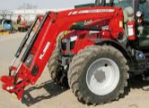 FL.3823
 FL.4018
 FL.4121
 916X Loader
 921X Loader
 926X Loader
 931X Loader
 936X Loader
 941X Loader
 946X Loader
 951X Loader
 956X Loader
 988 Loader
 FL.4125
 FL.4227
 FL.4124
 FL.4220
 FL.4323
 FL.4327
 FL.4621
 FL.4624
 FL.4628
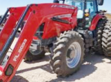 FL.5033
 DL95 Loader
 DL100 Loader
 DL120 Loader
 DL125 Loader
 DL130 Loader
 DL135 Loader
 DL250 Loader
 DL260 Loader
 L90 Loader
 L100 Loader
 L105E Loader
 L210 Loader
 1014 Loader
 1016 Loader
 1462 Loader
 1525 Loader
 1530 Loader
 232 Loader
 838 Loader
 848 Loader
 246 Loader
 1036 Loader
 1038 Loader
 1080 Loader
 856 Loader
 1010
1010 1020
1020 1030
1030 1035
1035 1040
1040 1045
1045 1080
1080 1085
1085 1120
1120 1125
1125 1140
1140 1160
1160 1165
1165 1180
1180 1190
1190 1205
1205 1210
1210 1215
1215 1220
1220 1225
1225 1230
1230 1233
1233 1235
1235 1240
1240 1260
1260